 |
 |
| Press release Persbericht | Nieuw | Projects | Embedded WebServers | BromSmurf Development | About Bromsmurf | Download | Links | WEBsite, Birds view |
Monitoring the washing machine |
||||
Introduction and problem definition |
||||
The washing machine and the laundry dryer are both located in the attic. As both machines are controlled by microcontrollers and sensors you never know how much time they will take to finish their job. There are two steep stairs from the first floor to the attic and we got tired of climbing the stairs just to see that the machines where still running. |
||||
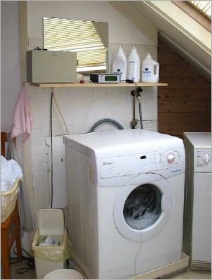
Washing machine and monitoring system Note the thin white cable comming from the glass door of the washing machine. On the machines side there is a thermometer which is connected to a Remote Sensor unit. This way the temperature of the machine can be monitored during the washing cycle. The Krokus Remote Sensor is a recent system and is apart from the monitor in this project. |
||||
The washing machine |
||||
Here is the washing machine with on the right the edge of the laundry dryer. In front of the mirror, to the left of the bottles, there is a small cabinet, a Remote Sensor unit, and a big cabinet: the washingmachine monitoring system. |
||||
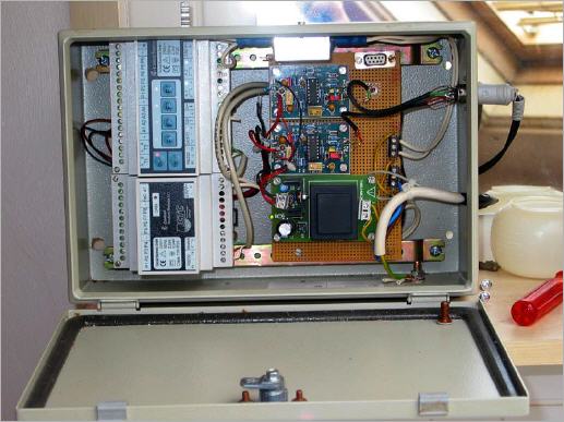
The monitoring system On the left are the CControl units. The big unit on top has the micro controller onboard. It gets the signals from the machines, analyses them and then sends the results to the lower unit, the transmitter. The transmitter then sends the code over the mains network to the receivers. |
||||
The CControl monitoring system |
||||
Now the box is open you can see how bulky CControl units are, they are on the left and mounted vertically. On the right you see the signal conditioners for both input channels and, towards the bottom, the power supply for the conditioners. The CControl units have their own supplies. |
||||
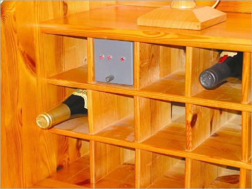
The washing mashine signalling device The device is seemly mounted between our wine. It is well visible yet not too obvious. |
||||
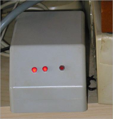
The washing mashine signalling device in action. From left to right the LED's mean: 1-washing mashine is running 2-heating is finished and 3-laundry dryer is running. This little cabinet can be placed anywhere, as long as there is a mains supply for power and data transmission. |
||||
Trouble shooting using our own tools |
||||
We had some trouble with the washing mashine some time ago. We noticed that LED 2 wouldn't light sometimes and first we investigated the functioning of the monitoring system. That was OK, so when do we start trusting our own systems first :-). |
||||
A temerature curve (RED line). This is a typical curve for the washing mashine heating to 40 degree C. First you see a drop in temperature when the fresh water comes in and, after 10 minutes, temperature starts rising at a rate of about 3 degrees per minute until the final temperature level is reached. |
||||
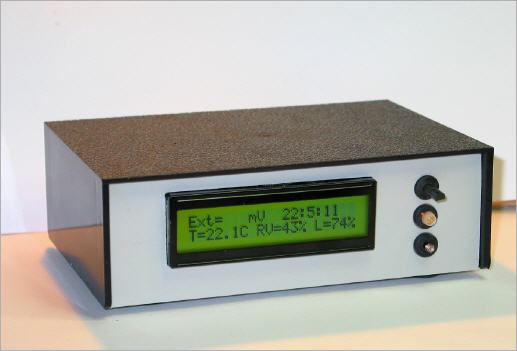
This is the new Krokus B with Bluetooh module. With this Krokus you can measure three standard parameters,T ,RH and light, plus an arbitrary value and transmit them to another device in another location which has to be within range (max 100 meters). |
||||
|
About Bromsmurf Bromsmurfs projects and experiments |
||||